How many types of inductor and their Applications?
Different types of inductor are provided here.
This also includes:
- Inductor Definition
- Types
- Applications
- Inductance
- Lot more
Keep reading
What is Inductor and what does it do?
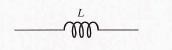
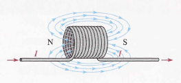
When a length of wire is formed into a coil, it becomes a basic inductor. The term coil and inductor are used interchangeably. Current through the coil produced an electromagnetic field, as illustrated. The magnetic lines of force around each loop (turn) in the winding of the coil effectively add to the lines of force around the adjoining loops, forming a strong electromagnetic field within and around the coil. The net direction of the total electromagnetic field creates a north and a south pole.
How does an inductor work?
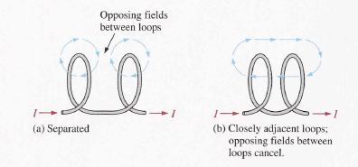
To understand the formation of the total electromagnetic field in a coil, consider the interaction of the electromagnetic fields around two adjacent loops. The magnetic lines force around adjacent loops is each deflected into a single outer path when the loops are brought close together. This effect occurs because the magnetic lines of force are in opposing directions between adjacent loops and therefore cancel out when the loops are close together, as illustrated. The total electromagnetic field for the two loops is depicted in part (b). This effect is additive for many closely adjacent loops in a coil: that is, each additional loops add to the strength of the electromagnetic field. For simplicity, only single lines of force are shown, although there are many:
What is Inductance?
when there is current through a conductor, an electromagnetic field is established. When the current changes, the electromagnetic field also changes. An increase in current expands the electromagnetic field, and a decrease in current reduces it. Therefore, a changing current produces a changing electromagnetic field around the inductor. In turn, the changing electromagnetic field causes an induced voltage across the coil in a direction to oppose the change in current. This property is called self-inductance but is usually referred to as simply inductance, symbolized by L.
“inductance is a measure of coil’s ability to establish an induced voltage as a result of a change in its current, and that induced voltage is in a direction to oppose the change in current.”
The Unit of Inductance
The Henry (H) Is the basic unit of inductance. By definition, the inductance of a coil is one Henry when the current through the coil, changing at the rate of one ampere per second, induced one volt across the coil. In many practical applications, milli henries (mH) and microhenries (μH) are the more common units.
The Induced Voltage Depends on L and di/dt:
The inductance (L) of a coil and the time rate of change of the current (di/dt) determine the induced voltage (Vind). A change in current causes a change in the electromagnetic field which, in turn, induces a voltage across the coil, as you know. The induced voltage is directly proportional to L and di/dt as stated by the following formula:
V ind = L (di/dt )
The formula indicates that the greater the inductance, the greater the induced voltage. also, it means that the faster the coil current changes (greater di/dt) , the greater the induced voltage.
How Energy is Stored in inductor?
An inductor stores energy in the electromagnetic field created by the current. The stored is expressed as follows:
![]()
As you can see, the energy stored is proportional to the inductance and the square of the current. When the current (I) is the henries, energy (W) is in joules.
Physical Characteristics of inductors
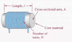
The following parameters are important in establishing the inductance of a coil: permit-ability of the core material, number of turns of wire, the core length, and cross-sectional area of the core.
Core Material:
As discussed earlier, an inductor is basically a coil of wire that surrounds a magnetic or nonmagnetic material called the core. Examples of magnetic are iron, nickel, steel. cobalt, or alloy. These materials have permeabilities that are hundreds or thousands of times greater than that of a vacuum and are classified as ferromagnetic. A ferromagnetic core provides a better path for the magnetic lines of force and thus permits a stronger magnetic field. Examples of nonmagnetic materials are air, copper, plastic, and glass. The permeabilities of these materials are the same as for a vacuum.
The permeability (μ) of the core material determines how easily a magnetic field can be established. The inductance is directly proportional to the permeability of the core material.
Physical Parameters:
The number of turns of wire, the length, and the cross-sectional area of the core are factors in setting the value of inductance. The inductance is inversely proportional to the length of the core and directly proportional to the cross-sectional area. Also, the inductance is directly related to the number of turns squared. This relation is as follows:
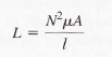
Where L is the inductance in henries (H), N is the number of turns of wire, μ is the permeability in henries per meter (H/m), A is the cross-sectional area in meter squared, and I is the core length in meter (m).
Winding Resistance:
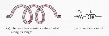
When a coil is made of a certain material. For example, insulated copper wire, that wire has a certain resistance per unit of length. When many turns of wire are used to construct a coil, the total resistance may be significant. This inherent resistance is called the dc resistance or the winding resistance (Rw).
Although this resistance is distributed along the length of the wire, it effectively appears in series with the inductance of the coil. In many applications, the winding resistance may be small enough to be ignored and the coil considered as an ideal inductor. In other cases, the resistance must be considered.
Winding Capacitance: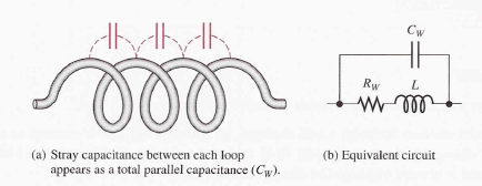
when two conductors are placed side by side, there is always some capacitance between them. Thus, when many turns of wire are placed close together in a coil, a certain amount of stray capacitance, called winding capacitance (Cw), is a natural side effect. In many applications, this winding capacitance is very small and has no significant effect. In other cases, particularly at high frequencies, it may become quite important.
The equivalent circuit for an inductor with both its winding resistance (Rw) and its winding capacitance (Cw). The capacitance effectively acts in parallel. The total of stray capacitance between each loop of the winding is indicated in a schematic as a capacitance in parallel with the coil and its winding resistance.
Types of Inductors
Inductors are made in a variety of shapes and sizes. Basically, they fall into general categories:
- Fixed inductor
- Variable inductor
both fixed and variable inductors can be classified according to the type of core material. Three common types are the air core, the iron core, and the ferrite core.
Adjustable (variable) inductors usually have a screw-type adjustment that moves sliding core in and out, thus changing the inductance. A wide variety of inductors exists. Small fixed inductors are frequently encapsulated in an insulating material that protects the fine in the coil. Encapsulated inductors have an appearance similar to a resistor.
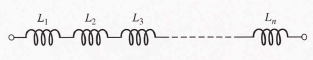
Series Inductors:
When inductors are connected in series, the total inductance, lt, is the sum of the individual inductances. The formula for LT is expressed in the following equation for the general case of n inductors in series:
LT = L1 + L2 + L3 + …………Ln
Notice that the formula for total inductance in series in similar to the formula for total resistance in series and total capacitance in parallel.
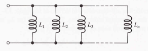
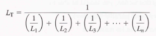
Parallel Inductors:
When inductors are connected in parallel, the total inductance is less than the smallest inductance. The formula for total inductance is parallel is similar to the formulas for total parallel resistance and total series capacitance.
When only two inductors are in parallel, a special product over sum form of the equation can be used:
![]()
Equal-Value Parallel Inductors:
This is another special case in which a short-cut formula can be used. This formula is also from the general equation and is stated as follow for n equal value inductors in parallel:

Handpicked links
I could not refrain from commenting. Welll written!